-
Step 1
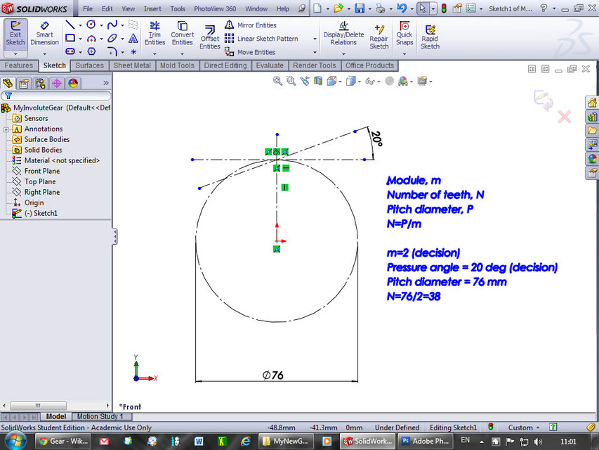
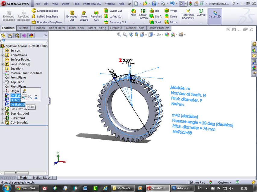
1) Make a sketch with a circle on the front plane. This represents the pitch circle that defines the centre of the tooth in radial direction. Dimension it. I chose a Pitch diameter, P=76 mm, but obviously you can choose any value.
-
Step 2
2) The module, m, expresses the size of the teeth and thus also the total number of teeth and the overall size of the gear wheel. I chose m=2.
Therefore the number of teeth, N, is N=P/m=76/2=38.
-
Step 3
3) Draw a vertical construction line through the centre and a horizontal tangent to the circle. The lines meet in the first point on the involute curve.
-
Step 4
4) Draw another construction line through this point at an angle of 20 degrees. This angle is called the pressure angle and 20 degrees is one of the most used standards, but it could be something else.
-
Step 5
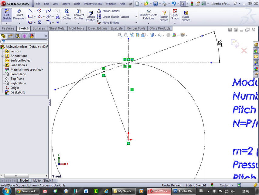
5) Draw a perpendicular construction line to the pressure angle line through the centre.
-
Step 6
6) Draw a construction circle through the centre and the point found in the previous step. This circle is the base circle for the involute. As you may know, an involute is the curve described by the end of a string wound around a cylinder. And the “string length” is the distance shown in the next step:
-
Step 7
7) Dimension that distance. (You have to make it driven in SolidWorks because the length is fully defined by the sketch). If you change the sketch, this measurement will update to a new value.
-
Step 8
8) I hide the sketch relations in this step to remove clutter from the images.
-
Step 9
9) I will now construct the “virtual” string when it is “unwound” a little more. Draw a centerpoint arc as indicated.
-
Step 10
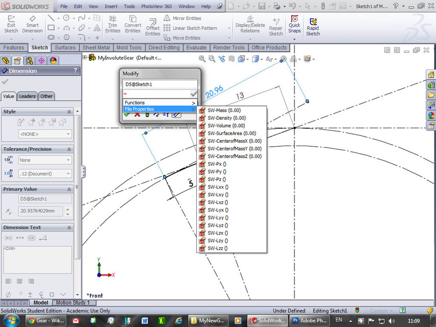
10) Dimension it to a nice round number, e.g. 5. This has to be an ARC DIMENSION. You click the two endpoints AND the arc itself, and the resulting dimension has a little arc over the number, showing that the dimension is measured through the arc instead of linearly.
-
Step 11
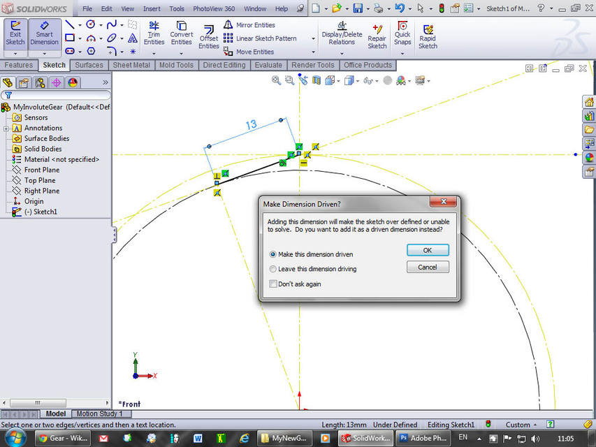
11) Now draw the radius and tangent through this new end point and dimension it.
-
Step 12
12) Press = when the dimension modify box is open to define an equation.
-
Step 13
13) Click the dimension for the first part of the string (length 13 mm in my drawing). This enters the value into the equation automatically.
-
Step 14
14) Click +
-
Step 15
15) Click the dimension of the “new piece of string” (length 5 in my drawing).
-
Step 16
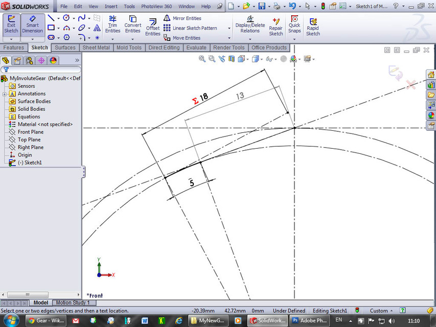
16) Click the green check mark in the dialog box. You’ll see that the new length is calculated from the existing dimensions (length 18 mm in my drawing). The endpoint is another point on the involute; and by changing the value of the arc, you can get ALL POINTS on the top half of the involute through this “graphic calculator”.
-
Step 17
17) Do a similar construction with an arc going the opposite direction to obtain an additional point on the involute.
-
Step 18
18) This time you subtract the arc length from the original value. You can also draw a point offset the initial value (13) along the base circle to get the lowermost point on the involute.
-
Step 19
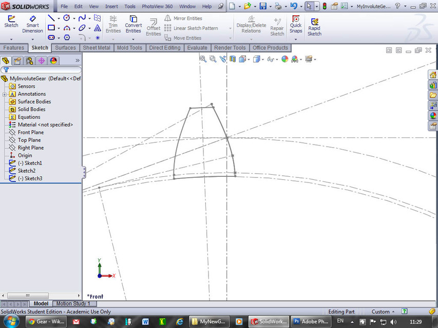
19) You can now draw the involute IN A NEW SKATCH using the constructed points.
-
Step 20
20) Use the spline tool to draw a spline through the 3 or 4 constructed points.
-
Step 21
21) Press ESC to end.
-
Step 22
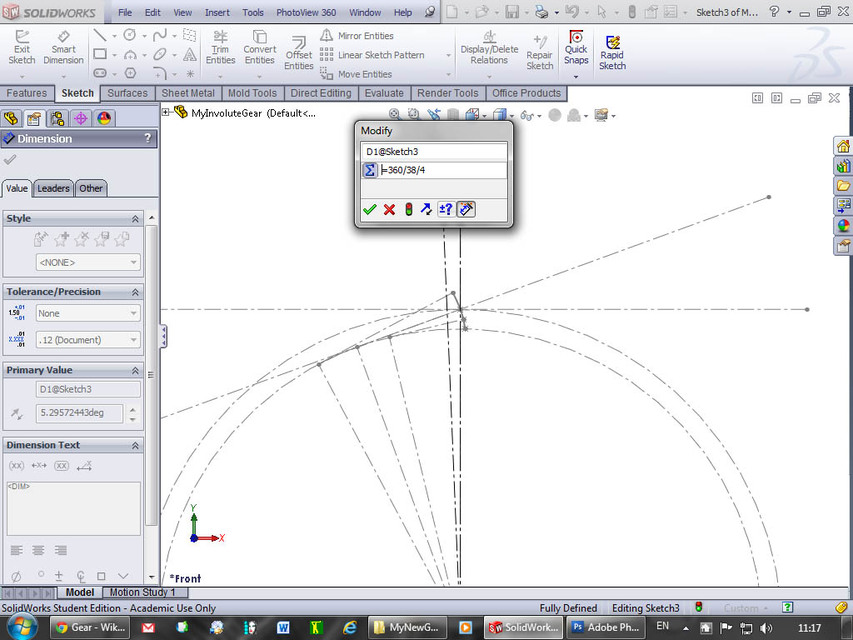
22) Draw a construction line that represents the centre of the gear cog. It is offset ¼ of the angle for one cog. You can do the calculations by punching in the numbers directly into the “Modify Dimension” box as “=360/38/4”.
-
Step 23
23) Mirror the involute by ctrl-clicking the spline and the centreline and choosing “Mirror Entities”.
-
Step 24
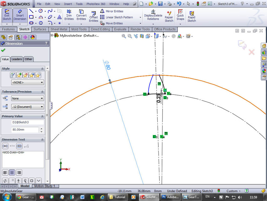
24) At this stage we need to draw the circle that defines the outer size of the gear. The diameter is defined by P+2*m = 76 mm + 2*2 mm = 80 mm.
-
Step 25
25) When you look closely, you see that the involute is a tiny bit too short to reach the outer contour. This needs to be fixed.
-
Step 26
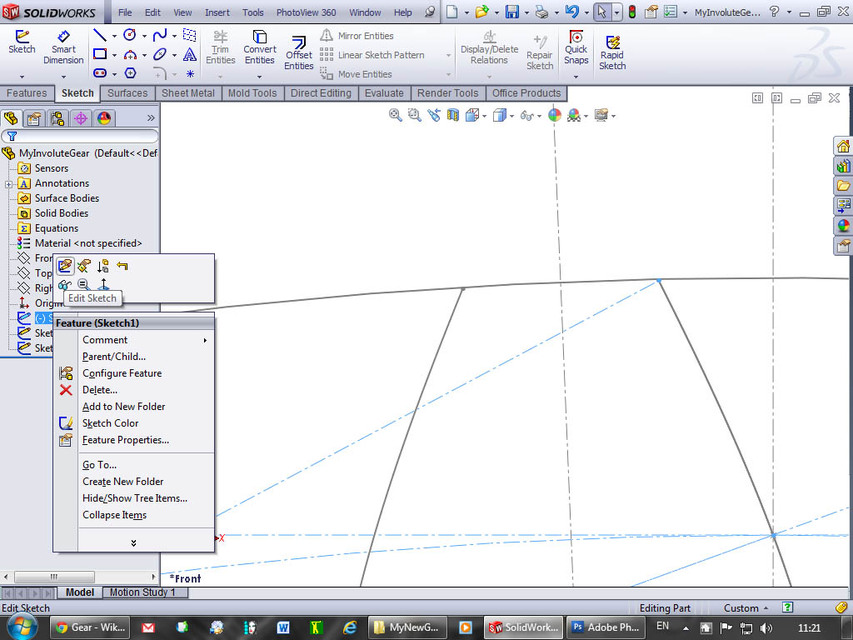
26) Go back to the first sketch and right-click it to edit. Increase the length of the arc from 5 mm to say 5.5 mm. Due to the parametric nature of the software, everything updates without you having to do anything else.
-
Step 27
27) Return to the present sketch and verify that the involutes now extend beyond the outer diameter.
-
Step 28
28) Use Power trim to cut off excess parts of the involutes.
-
Step 29
29) We need to add a small clearance for the teeth inside the involute diameter. Extend the tooth downwards with lines parallel to the normal construction line.
-
Step 30
30) I chose a .25 mm extension/clearance.
-
Step 31
31) Mirror the profile.
-
Step 32
32) Draw the base (inner) circle.
-
Step 33
33) We are now ready to extrude the gear. Make a new sketch on the front plane …
-
Step 34
34) … and choose “Convert Entities”
-
Step 35
35) Select the inner circle and click the green check mark.
-
Step 36
36) Extrude the base cylinder. I chose a 12 mm wide gear wheel.
-
Step 37
37) Make a new sketch on the front plane, choose “Convert Entities” again and check “Select chain”.
-
Step 38
38) Click on the gear tooth profile and click OK.
-
Step 39
39) Do another extrude …
-
Step 40
40) … using the Up to surface and select the front face of the gear.
-
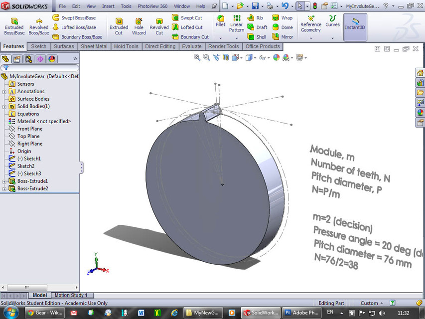
Step 41
41) This is the result: The gear wheel with one tooth.
-
Step 42
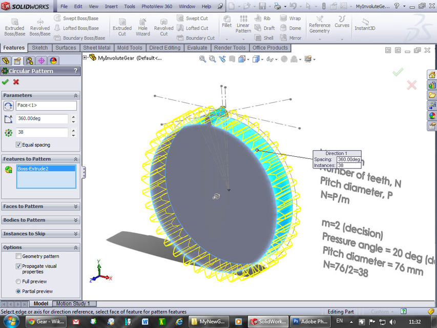
42) Choose “Circular Pattern” to copy the tooth, select the outside face and the tooth as “Feature to Pattern”. Specify 38 instances, equal spacing over 360 degrees and click OK.
-
Step 43
43) The gear wheel is almost complete.
-
Step 44
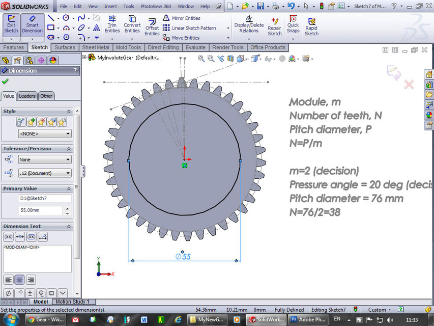
44) Cut away the centre with a 55 mm circle on the front face.
-
Step 45
45) And “Cut-Extrude Through All” for improved visibility.
-
Step 46
46) Hide the sketches by selecting all and choosing “Hide” (the glasses).
-
Step 47
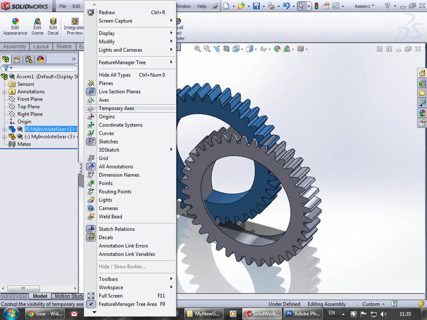
47) Now comes the best part: Verification of the design. Save and choose “Make Assembly from Part”.
-
Step 48
48) Click the green checkmark for OK. This gives an assembly with the gear wheel at the origin.
-
Step 49
49) Ctrl-drag a second copy of the gear wheel into the main window.
-
Step 50
50) Choose “View Temporary Axes” to show axes for mating.
-
Step 51
51) Ctrl-select the two centre axes and click the mate (paperclip) icon that pops-up.
-
Step 52
52) Add a distance mate of 76 mm (= the pitch diameter) which is also the distance between the gears when they have equal size.
-
Step 53
53) Mate the temporary axis of the second gear to the assembly top plane …
-
Step 54
54) … and mate the front faces of both gear wheels.
-
Step 55
55) We are now almost ready, but the first gear is fixed and can’t turn. Right-click on the first gear wheel (the one with that has (f) in front of its name) and choose “Float”.
-
Step 56
56) Now it can move everywhere so we need to fix it so it can only rotate. Mate the temporary axis to the assembly top plane …
-
Step 57
57) … Mate the temporary axis to the right plane …
-
Step 58
58) … and the front plane to the assembly front plane. Now both gear wheels can rotate independently but they stay centered.
-
Step 59
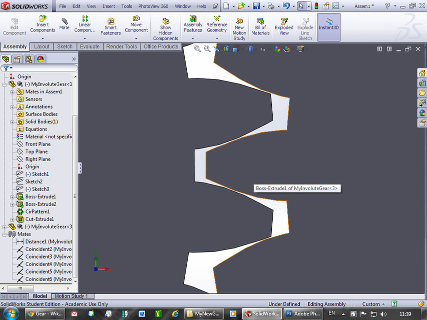
59) Go to a front view and zoom into the teeth that mesh.
-
Step 60
60) We need to cheat a little bit to make the next step work, because the gears are too perfect and are always touching.
-
Step 61
61) Right-click on the distance mate and change it by a small amount …
-
Step 62
62) … e.g. from 76 to 76.1 mm. This gives a little slack that’s necessary for the next steps to initiate.
-
Step 63
63) Rotate one of the gear wheels so they do not touch.
-
Step 64
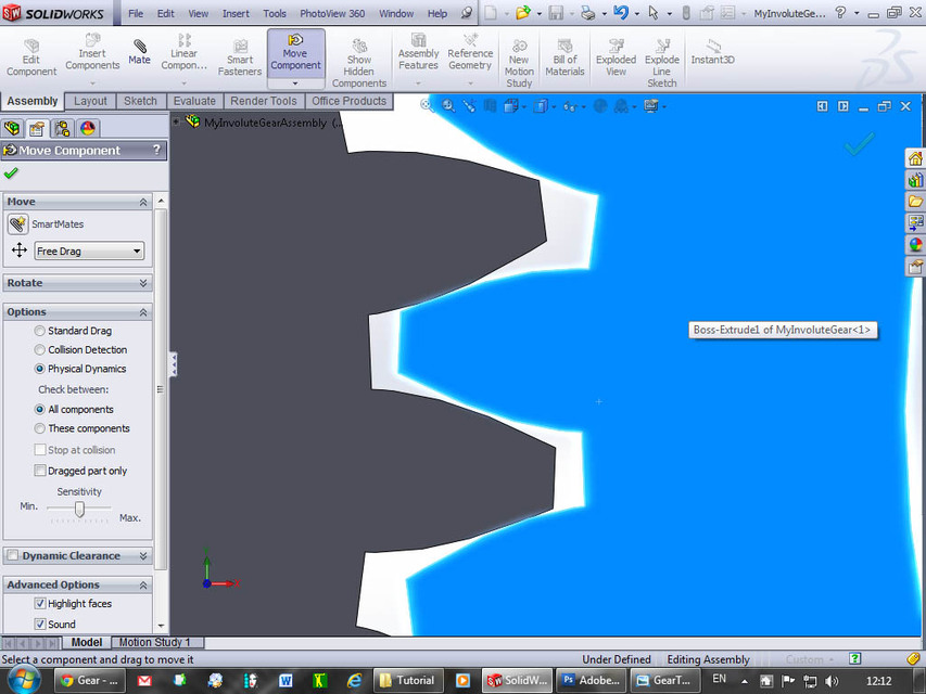
64) Choose “Tools->Component->Move” from the top menu.
-
Step 65
65) Click the radio button for “Physical Dynamics”.
-
Step 66
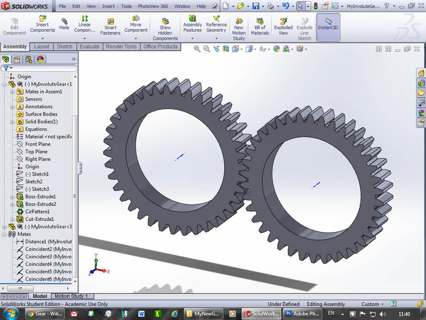
66) Click and drag one of the gears, and observe that the other gear follows along and the involutes mesh very nicely. You can go backwards and forwards. This is SO COOL :-)
-
Step 67
67) We’re done. We have designed involute gears and verified that they actually work according to design intent.